Project conducted by the FactoryLab industrial consortium with cross expertise of CEA-List, CETIM and ENSAM-Paris in collaboration with Isybot, Naval Group, Stellantis and Safran.

Manually guided machines, from manipulators to cobots
Industrial manipulators are machines that allow operators to move loads without carrying them. They are different from manipulating robots, and are categorised as lifting equipment[1]. When they incorporate functions derived from robotics such as virtual guides or software working space limitations, they are known as cobots or IADs (Intelligent Assist Devices).
In industrial robotics, the manual guidance mode makes it easier to teach points by programming; it can also be used in load-carrying assistance applications. The term cobot has also become common for robots that offer such functions. As part of the subject of «Physical assistance to operators», the FactoryLab consortium supports the development of innovative technologies that address industrial needs where the existing physical assistance resources are not satisfactory, such as the assembly of large parts in aviation (projet MANIPRES), or work with tools on cluttered workstations (projet BAR10).
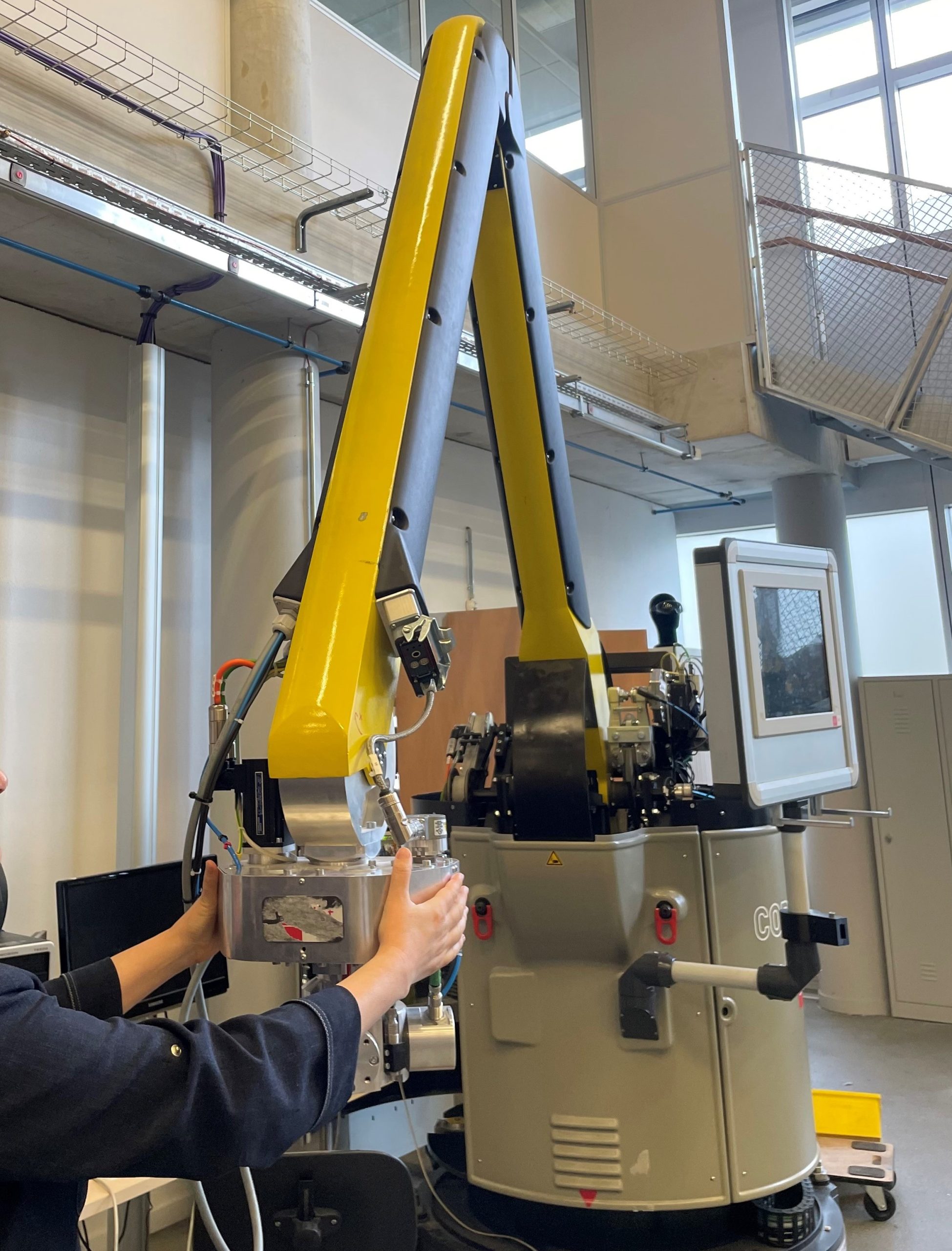
Photo credit: CEA-List
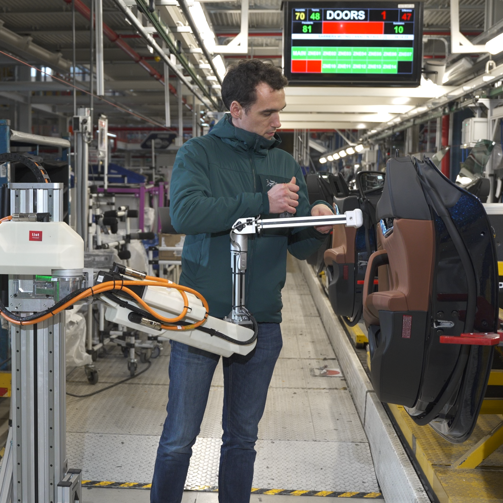
Photo credit: CEA-List
Assistance resources that are actually usable
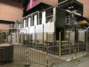
Industrial manipulators are frequently installed in factories, where they remain underused, particularly for medium-sized loads of about a dozen kg: when the load can be transported manually, operators may prefer to work without assistance, which they see as inconvenient or slow, even at the cost of their own health and safety. The issue is relevant in many operating positions of our user manufacturers, who find that loads that are handled repeatedly are sources of MSDs (musculoskeletal disorders) and difficulties to stay at the position.
One of the factors of such underuse is mechanical: while these systems take over the load (weight of the object to carry), they can demand significant effort for setting into motion and controlling movement.
To objectively identify that difficulty, ergonomics specialists can use a dynamometer to measure forces and recommend a level that must not be exceeded[2]. These measurements reflect[3] the difficulty to control movement only partly and can only be carried out after the event.
When a working position is being designed, questions about the feasibility and sizing of the assistance resources arise: can assistance that compensates for gravity enable compliance with ergonomics limits? How can the performance of assistance resources be specified in order to stay within those limits?
In the case of collaborative robots, robot manufacturers do not currently provide the performance characteristics of their manual guidance modes and comparisons remain subjective[4].
Modelling and measurement of mechanical transparency
An elementary yet instructive model
The concept of transparency was introduced for remote operation with force feedback[5]: the aim is to allow the operator to feel the object that is manipulated or the environment touched by the effector as if they were interacting directly. In the case of load-carrying assistance or manual robot guidance, that ideal of transparency would amount to not applying any effort, at the same time retaining the ability to control the movements of the load.
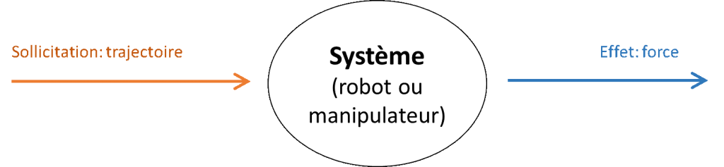
The behaviour of the system to be characterised is an external mechanical behaviour, seen from its grasp by the operator. The concept of mechanical impedance[6] is used to define how a system resists movement. Even though it is complex, such behaviour may be characterised locally for a given configuration, along a direction.
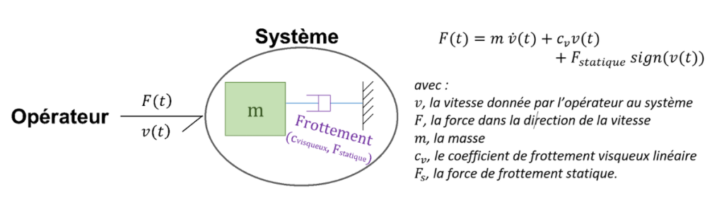
For the systems of concern to us, a simple physical model most often allows a description of impedance. It is made up of an apparent mass and two viscous and static friction components.
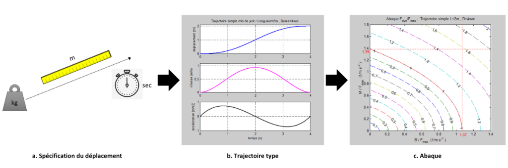
This model makes it possible to predict the forces in the direction of the required movement, providing the time profile of speed and acceleration are known. How can that profile be known in advance while specifying the assistance resource? In a natural movement of the arm, it has been shown[7] that the path is one that minimises jerk (time derivative of acceleration). Based on that property, we build a typical path that corresponds to a movement where the length and duration are specified[8]. That path does not reflect inter-personal variability, but the effect of the constraints of the task on the required speeds and accelerations. Based on the typical path, tables can be built to define the parameters of the impedance model that will allow compliance with ergonomic force limits.
Measuring devices
We propose the use of an external device that will stress the moving system and measure the reaction forces. Stress is applied in displacement along a direction. The measured force is the interaction force.
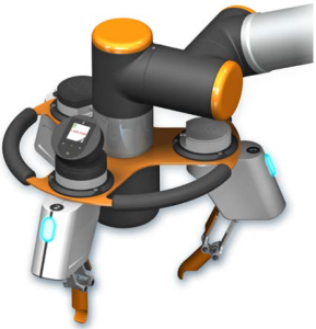
Three external measurement systems have been proposed. The first two apply rectilinear movement through a linear rail; in the third, the movement is not constrained:
- The first one is motorised and makes it possible to impose excitation paths. The movement is measured by a motor encoder;
- With the second device, movement is imposed manually along the rail and measured by a magnetic linear encoder;
- The third one is mobile and the movement given by the operator is measured by an inertial unit.
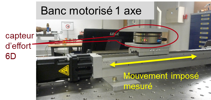
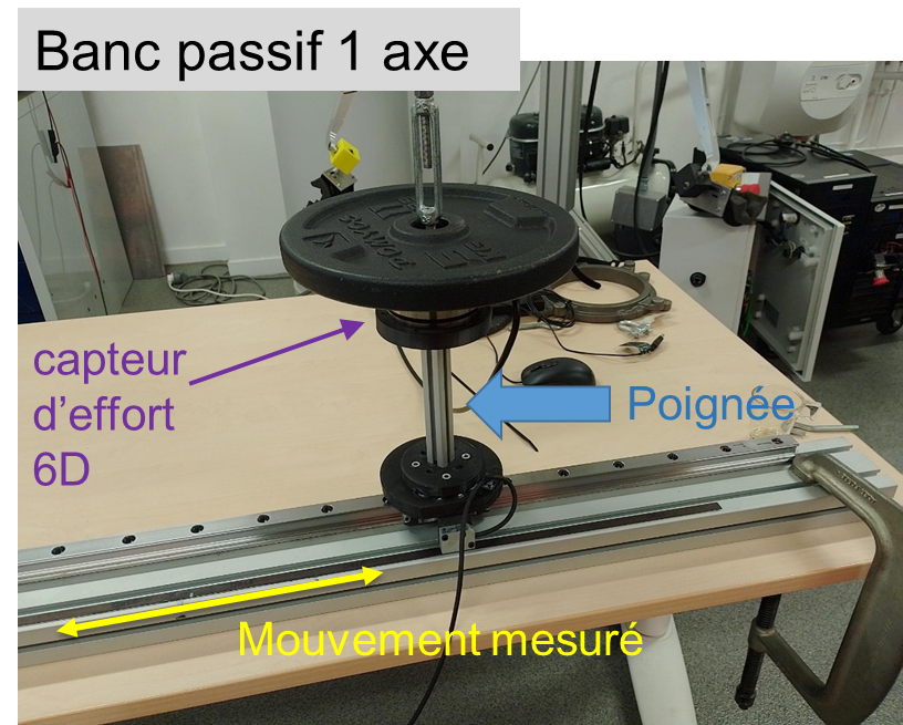
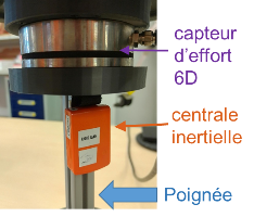
Figure 4: The three prototype measurement devices
Photo credits: CEA-List
We have used a six-axis force sensor to assess not just the force in the direction of the movement, but also lateral forces.
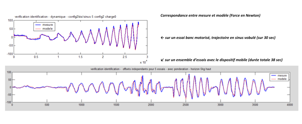
In the case of the motorised device, we uses paths of different types: speed stages that make it possible to separately identify the friction model, wobble sinus and minimum-jerk paths. In the case of manually activated devices, the recommendation is to combine tests with the paths naturally used by the operator and excitement tests[9].
The measured data were filtered[10] and the simple model was identifiable by least squares. Indicators were calculated to define the quality of identification (identifiability of parameters and difference between measurement and model). In manual tests, tests were combined with paths of different types to obtain robust identification.
Practical test of measuring equipment
Identification of a physical model
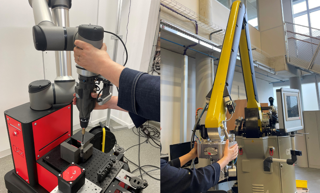
A model was identified that connects force and the movement in the direction of movement. We were able to test identification in five different systems:
- Two collaborative robots, one with cable and ball screw actuators, the other with conventional actuators (with gears[11]);
- Two industrial handling solutions: a load manipulator with active assistance functions, and a gantry with a carriage and travelling crane;
- A passive articulated (spring balanced) arm that assists tool carrying.
On the basis of those tests, where the primary goal was to validate the measuring equipment and identification, we were able to see that systems can be categorised according to the values of the parameters obtained and their relative influence: inertial behaviour (dominant mass) for the industrial manipulator and handling gantry. Very viscous behaviour (dominant coefficient) for the collaborative robot with conventional actuators.
Consideration on the practice of tests
The measurement configuration is defined by:
- The load[12];
- The direction of the movement;
- The orientation of the effector;
- The configuration of axes in the case of an articulated system[13];
- And for active systems, the configuration of control[14].
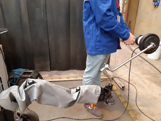
Photo credit: Naval Group
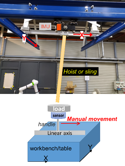
Photo credit: CEA-List
In the case of measurement with a rail, the fixed position of the rail constrains the test configuration, but in the case of the mobile measurement system, that configuration can easily vary when the tests are repeated. In that case references must be taken (visual and/or material) to keep the same configuration when tests are repeated[15].
With the exception of the gantry, the simple model with one mass makes it possible to estimate the force.
In the case of the gantry, the simple model with one mass is not suitable and a model with two masses was adopted[16]. Its identification is more complex: a frequency model can be identified providing very exciting stresses are applied. We have opted for manual stress with an additional measurement: the movement of the carriage which corresponds to the second mass was observed by an inertial unit (see Figure 7).
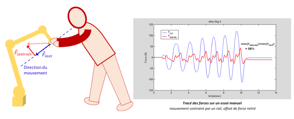
Importance of lateral forces
The importance of lateral force reflects a difficulty to precisely control the movement in a direction imposed by the operator. Lateral forces were measured during tests and we have proposed criteria that reflect the proportion between the lateral force and that in the direction of the movement.
In the tests carried out with a rail, lateral forces are transferred to the rail and are not imposed by the operator during the test. We observed significant amplitudes, even with systems that are qualitatively easy to put into motion.
In the case of a ‘conventional’ collaborative robot, the internal forces generated by the constraint of the fixed rail are significant, which means that the test assembly must be strong. These tests considerably activate the flexibility internal to the robot and the residual flexibility of the test assembly, which is not the case when the robot is used ‘naturally’. The question of the specification of the rigidity conditions of the assembly remains open.
In the cases of tests with the mobile system, the rigidity of the operator determines the level of lateral forces. The test conditions are therefore more natural, but subject to inter-personal variability.
Rather than measure the force of resistance of the system which ‘prefers’ another movement direction, the deviation of movement of the system subjected to a pure force can be measured[17],[18]. That criterion may be more physically repeatable but requires a fairly precise measurement of the position in space[19],[20].
Conclusion
Defining and using mechanical transparency criteria
For a given system, the level of force may vary widely depending on the level of speed and acceleration required for carrying out the movement. That is the case of the forces defined in the ergonomics standard NF X35-109[21]. Characterisation through the three parameters of the impedance model (see Figure 1) is more general and makes it possible to predict the level of force that the operator must apply on the system to move it within a given time.
One of the limits of the characterisation is its local nature. Dependence on the configuration and direction may be anticipated depending on the structure of the system. In the more complex case of articulated robots, configurations and directions can be selected on the cube of standard ISO9383. The choice of test configurations may also be defined depending on the task to perform.
The difficulty of controlling the movement finely, a question that remains open
What is more difficult is the characterisation of the ease or difficulty of controlling the movement finely.
Lateral forces, i.e. the effort to maintain the path on a precise line, are one of the components of the difficulty to control. We measured them, but they are difficult to predict using a simple model. The criteria associated with that measurement, whether it is the ratio between the lateral force and the force aligned with the movement, or the angle between the applied force and the resulting movement, depend closely on the amplitude of the forces.
Another component of the difficulty in controlling is illustrated by the case of the gantry where the movement of an offset mass (carriage or beam) is not in phase with that given by the operator. That is reflected by an order 3 impedance model and associated time constants[22].
Static friction is a source of difficulty in controlling. However, in the systems we have tested, static friction is only a minor, even negligible component.
The compliance (flexibility) of the system can suffice to make small movements with minimum effort. Compliance can also help an insertion operation. But in the case of a free system, it will take a new balanced position when it is released by the operator, which can lead to a precision problem[23].
Lastly, two-hand manipulation, which is often used for precise operations, introduces additional complexity if measurement in representative conditions is to be achieved.
One alternative to a model-based approach is the performance of dexterity tests[24] by operators, which method requires standardised but significant testing and the repetition of tests by a sufficient number of individuals.
Having a measurement kit
The measurement systems prototyped during the project and the associated processing are not to date engineered for industrial use. User manufacturers are particularly interested in the mobile measurement system, which allows ergonomists to objectively assess the manipulation forces on the installed equipment. The partners and CEA-List are open to signs of interest to transfer the expertise to a company that is looking to provide a measuring service or kit.
[1] In the article ‘Is my cobot a robot or a loadhandling device? ‘ (Case Story COVR, 2021) Sylvain Acoulon addresses the question of the different applicable standards depending on whether the system is considered to be lifting equipment of an industrial robot.
[2] See for example ‘Guide pratique d’ergonomie en conception industrielle/Practical guide to ergonomics in industrial design’, Jean-Francois Thibault (sous la direction de/edited by), bilingual, Octares Editions, 2017].
[3] As part of the assessment of push-pull efforts while using a handling truck, INRS has shown that measuring force along the movement direction alone leads to significantly underestimating the effort [‘Les efforts de tirer-pousser – points de repère’, K. Desbrosses and al., INRS, ND 2365, Hygiène et sécurité du travail-3e trimestre 2012].
[4] The assessment of manual guidance was recently addressed by the robotics laboratory of the university of Munich [Kirschner, R. J. et al. Manual Maneuverability: Metrics for Analysing and Benchmarking Kinesthetic Robot Guidance”, in 2022 IEEE/RSJ International Conference on Intelligent Robots and Systems (IROS), Nov. 2022].
[5] ”What constitutes an “ideal” telemanipulator? Intuitively a reasonable response would be: An ideal telemanipulator is one that provides complete transparency of the interface. In other word the operator feels as if the task object were being handled directly.“ excerpt from [G. J. Raju, G. C. Verghese, and T. B. Sheridan, “Design issues in 2-port network models of bilateral remote manipulation,” in 1989 International Conference on Robotics and Automation Proceedings, 1989, pp. 1316–1321 vol.3].
[6] The term impedance comes from electrical engineering and has been since reused in mechanics, acoustics, and robotics. The word “impede” reflects hindrance or braking in the context of movement. It is most commonly used in a context of linearised models, as a transfer function. Neville Hogan introduced the term into the area of human motor control and in that of the control of robots. Many works can be found that cover the identification of the impedance of the human arm during simple tasks.
[7] [T. Flash and N. Hogan, “The coordination of arm movements: an experimentally confirmed mathematical model,” J. Neurosci., vol. 5, no. 7, pp. 1688–1703, Jul. 1985].
[8] In the case of movement over a sufficiently long distance, the typical path incorporates a phase at constant speed which corresponds to a working phase.
[9] To-and-fro movements are requested, either with (sudden) stops or continuous (smoother) movements with speed modulation. Different dynamics make it it possible to achieve improved identification quality.
[10] In the case of the mobile device, speed is obtained by integrating free acceleration and the drift is corrected by using the fact that each measurement starts and ends at zero speed.
[11] more particularly in the case of harmonic drives.
[12] The load is added to the apparent mass of the system and the friction level generally increases with the load.
[13] In our tests, that was true of collaborative robots that were poly-articulated, and of the assistance arm. In an articulated system, physical phenomena of inertia and friction are located at the axes and in the moving bodies, and so the apparent impedance will depend on the configuration of the axes and the direction of movement. In the case of a Cartesian movement system (XY, or XYZ) only the direction of movement is important, and not the position of each axis.
[14] For example, when a robot is in manual guidance mode, blocking Cartesian movement axes is not without effect (function offered by some manufacturers). The declared parameters of the mass of the tool can also have an influence.
[15] Variability during tests is ultimately reduced by repeating them and combining them in the digital resolution.
[16] The force predicted by the model with two masses depends on the offset between the movement of the two masses. The upper bound of the force is obtained with the hypothesis of phasing the two movements.
[17] Corresponds to the transparency index proposed by Métillon for characterising suspended cable systems. In such systems, inertia and friction are very low, so that the lack of transparency is mainly this anisotropy [Métillon, M., Charron, C., Subrin, K., Caro, S. «Stiffness and Transparency of a Collaborative Cable-Driven Parallel Robot». in Advances in Robot Kinematics 2022. ARK 2022. Springer Proceedings in Advanced Robotics, vol 24. Springer, 2022] [Métillon.M., Modelling, Control and Performance Analysis of Cable-Driven Parallel Cobots. Doctoral thesis, École centrale de Nantes, June 2023].
[18] Also corresponds to the criterion incorrectly named “Motion steadiness” proposed by [Kirchner&al. 2022, op cit].
[19] The protocol proposed by [Kirchner&al. 2022, op. cit.] uses a laser tracker to measure the direction of the movement obtained under the stress of a pure force. In the case of a robot, it would be possible to use the position measurement, providing the direction of application of the force is calibrated in the robot reference.
[20] Our mobile measuring device does not provide sufficient precision about movements.
[21] The initial (starting) force and that of stopping (braking) depend on acceleration and also speed depending on the dominant parameters of the impedance model. The maintaining (or rolling) force depends on speed. These forces are defined in the French standard [NF X35-109: 2011, Ergonomie – Manutention manuelle de charge pour soulever, déplacer et pousser/tirer – Méthodologie d’analyse et valeurs seuils, October 2011].
[22] The difficulty in controlling may be addressed by considering that the operator regulates their force to obtain the movement or the speed required, and by analysing the problem like that of regulator synthesis. Even though human control cannot be assimilated with control that is automatic, and what is more, linear, the assumption may be made that some of the difficulty offered by a system to be controlled is retained. Such an approach is developed in particular in studies that model the behaviour of aircraft pilots. An overview can be found in the article [Scibilia, A., Pedrocchi, N. & Fortuna, L. Human Control Model Estimation in Physical Human–Machine Interaction: A Survey. Sensors 22, 1732, Feb. 2022].
[23] For example, in the case of learning of points by a robot in manual mode.
[24] An example of a dexterity test in remote operation can be found in [David, O. et al. Digital assistances in remote operations for ITER test blanket system replacement: An experimental validation. Fusion Engineering and Design 188, 113425, March 2023].
Author: Catherine BIDARD, METRAMM Project Manager, CEA-List